
Controlling
YAMAHA W5/W7 with the PC keyboard
Other beautiful parts of my darling are buttons that gradually cease to work or you must use a rough violence to succesfully cause a desired action. Once I tried to repair the microswitches and it´s really terrible to get to them. I wanted to put there other ones, but YAMAHA must have everything special and non-standard. It would have been necessary to drill additional holes into the board to put there standard microswitches. Unfortunatelly I was very busy then with my music band and it wasn´t possible to pause. So I paid a lot of money for the professional repair.
But break-downs of individual buttons started to appear again, so I decided to carry out a more radical action – to use a PC keyboard. It was necessary to make a „black box“ which processes keyboard data and then sends them through MIDI to the instrument. This „black box“ must not block input data from MIDI in but it have to insert the keybord data properly there. The brain of the „black box“ is an ATMEL microprocessor - AT89c2051 (my favorite one) with 12 Mhz crystal, there is also an optocoupler, a transistor, some capacitors and resistors, three (or four) connectors.
Power is resolved with an external power supply 7-12V AC or DC. Two LEDs can be put there: one of them indicates incoming midi data, the second one keyboard presses. Further it is possible to put two buttons: one of them is the GS reset, the second one is the panic-button. Following functions are accessible through the PC keyboard:
- PANIC - CTRL+BREAK
- GM reset – CTRL+ALT+F1
- GS on - CTRL+ALT+F2
- GS off - CTRL+ALT+F3
- Yamaha restart - CTRL+ALT+DEL (a common action for Windows users)
- And then all the Yamaha buttons are simulated.
I use my „black box“ for one year and it still seems to be fully functional. So this uggly Yamaha microswitches can commit hara-kiri. When I´m getting crazy, I can simply smash the PC keyboard (with a hammer) and then to buy a new and cheap one.
Printed board is designed in relation to other future applications. It is possible to put an extra connector (+5V, GND and three unused microprocessor IO pins). Then it is possible to put X25043 (serial Eeprom with WD timer).
Obrázky z akce
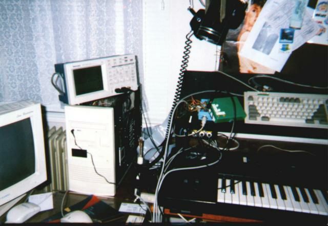 | In the course of development I made a mess like this | 44 kB |
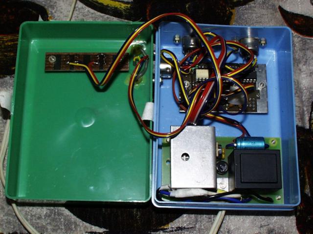 | Look how nicely I made it | 50 kB |
Ke stažení
 | schematics, firmware etc. | 299 kB |
(C) 2005 Klapka Design, All Rights Reserved.
last actualization 2005/09/28